Technical Specification

Clock Timer
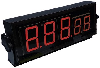
Actual Time of XX.XX.100 to XX.XX.104 will show as XX:XX.10
Actual Time of XX.XX.105 to XX.XX.109 will show as XX:XX.11
3” (75mm) Amber colour Digit Height - 1/10, 1/100th sec)
Viewable at 200’ (61 meter)
- Metal Housing: 8” x 16” x 2 “ (203 x 406 x 51mm)
- Indicates time to 1/100th of a second
Actual Time of XX.XX.100 to XX.XX.104 will show as XX:XX.10
Actual Time of XX.XX.105 to XX.XX.109 will show as XX:XX.11
- Large Seven Segment display
3” (75mm) Amber colour Digit Height - 1/10, 1/100th sec)
Viewable at 200’ (61 meter)
- Environment: Dust resistant
- Wall Mounted Bracket
- Wire Connectors: Two RJ-12 style Modular connectors
- Operating power requirements: 12V1A DC : 2.5 mm x 5.5mm socket

Foot Switch
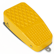
(Standard aluminum foot switch)
(Standard aluminum foot switch)
- Cast aluminum material for industrial environments with three mounting holes in the base.
- Foot pedal and pedal base are constructed of rugged cast aluminum for an industrial environment.
- Size: 1.69" x 2.56" x 5.31" (43 x 65 x 135 mm)
- Specifications: EN60529 IP20, CE, UL,
- Operating power requirements: 12V1A DC (Supplied from Clock Timer)
Finish Switch
No moving parts : sensor
System ready (Blue steady)
Clock Stop (Red flash)
Through wall
- Construction: Plastic, Brass, Aluminum
- Activation : Dielectric Capacitive Sensing
No moving parts : sensor
- Integrated LED indicator lights:
System ready (Blue steady)
Clock Stop (Red flash)
- Mount Design:
Through wall
- Operating power requirements: 12V1A DC (Supplied from Clock Timer)
Competition Controller
Controller
Competition
Judge timer ready (Blue steady)
False\Anticipated Start Stop (Red steady with Red flash of false\Anticipated start route)
Output:
Internal: 2 high output speakers 99-105dB .
External: 1.8mm Audio output
Start Sequence indicator:
Single: None
Training Mode: Single Independent or Double route with Manual-Judge Activated
Competition Mode: Manual-Judge Activated
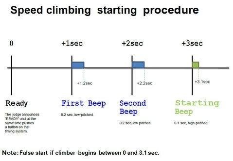
IFSC Judge activated start sequence sound
Controller
- Connects two single routes for controlled unison timing
- False start detection & identification
- Anticipated False Start 0.1 sec
- Audio & Visual indicators
- Mode of operations:
Competition
- Visual Indicators
- 3 LED multi color indictor lights (Route 1, Timer, Route 2)
Judge timer ready (Blue steady)
False\Anticipated Start Stop (Red steady with Red flash of false\Anticipated start route)
- Sound indicators
Output:
Internal: 2 high output speakers 99-105dB .
External: 1.8mm Audio output
Start Sequence indicator:
Single: None
Training Mode: Single Independent or Double route with Manual-Judge Activated
Competition Mode: Manual-Judge Activated
IFSC Judge activated start sequence sound
Connection Wiring
- Multiconductor flat (oval) cable – 6 conductors
- Copper conductors: 26 AWG (0.16x7)x6C
- Polypropylene insulation (PP6331 ID: 0.95±0.05)x6C
- Overall polyvinylchloride jacket PVC NOUL 65P
- Temperature Range -20°C to 60°C
- Voltage Rating 150 Volts
- Operating power usage: 12V1A DC
- Connector: RJ-12 style Modular connector
- DCV 2.5 mm x 5.5mm power socket
- Judge Switch
- 18-20’ Cloth woven cable
Integrated ergonomic handle
Integrated switch
1/4" TS connector
Route Mounted Indicator Lights - Construction: Plastic
- Integrated LED indicator lights:
- System Ready (Blue steady)
Race Start \ Valid Start (Green steady)
False Start \ Anticipated Start (Red steady with Red flash of false\Anticipated start route) - Mount Design:
- Surface mount
Through wall - Operating power requirements: 12V1A DC (Supplied from Competition Controller)
Market: Worldwide with exclusion to countries of US or Canada technology restrictions
Service Life: Design for 7-10 year
Environment: Indoor use (not waterproof)
Operation: Manual \ semi auto
Warranty: 1yr mfg

